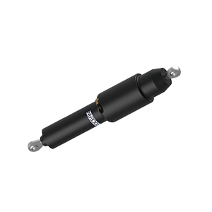
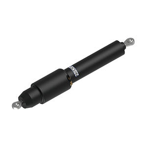
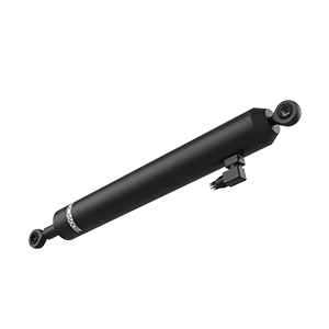


To size a subsea linear actuator for an ROV hatch or sampling mechanism, work out the stroke from the mounting geometry. Then calculate the required push and pull forces and speed at the actuator throughout the motion. Check both the end positions and the loads between them.
Calculate stroke from the mounting points
Mark the fixed and moving actuator mounts on the assembly drawing and measure the distance between them with the mechanism open and closed. For a hinged mechanism or linkage, sweep through the full motion to find the shortest and longest pin-to-pin distances. The difference is the travel the mechanism needs. Check both distances against the actuator’s retracted and extended lengths and allow room for assembly tolerances and end stops.
Moving a mounting point can change both travel and force for the same opening angle. Include mounting coordinates or a drawing reference when asking for a configuration.
Calculate push and pull separately
At each position, resolve the effects of net submerged weight, friction, inertia and water flow into force along the actuator axis. Record push and pull separately, using a consistent unit such as N or kgf. For hinged mechanisms, the lever arm changes through the motion. Check the start of movement and positions near the end stops, and account for loads that occur at the same time.
Suppose an illustrative hatch linkage needs 180 N to start moving, 130 N at mid-stroke and 260 N near the end of travel. The 260 N case must be checked at the required speed at that position. The return stroke needs its own pull-force calculation.
Read the TG050 specifications
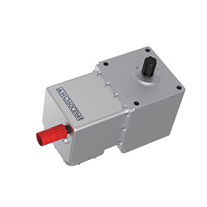
The TG050 product page lists a nominal force of 50 kgf, 200 W power and a 12–36 VDC supply. Its technical table lists a speed of 10 mm/s. Use these values for an initial shortlist, then ask for the available force and speed under the intended supply, load and duty cycle. The public table leaves the load and depth associated with the listed speed unspecified.
| Sizing input | What to provide |
|---|---|
| Stroke and mounting | End-position dimensions and shortest and longest mounting distances |
| Push and pull | Peak loads in both directions and where they occur |
| Speed and duty cycle | Target move time, frequency and duration per move |
| Environment and interfaces | Water type, depth, power supply, connector clearance and drawing |
Product references
TG050 product page https://hydrocean.net/200w-12v-36v-electric-joggers-hydrocean-tg050.html
ROV and AUV actuator selection guide https://hydrocean.net/articles/geo-3f42e82b-e5d6-4e2a-b1f2-53c55b725138.html